Long Run Oil
System™
The oil reservoir capacity has been enlarged to allow the
engine to operate for a period of 3,000 hours. Consideration was given to the
normal oil consumption of the engine under any load conditions, as well as to
the maximum oil consumption expected as the engine wears.
An oil suction
strainer extends into the reservoir to sufficient depth to ensure that the
engine will to continue to have adequate lubrication throughout the extended
service interval. Baffles, located in the oil reservoir, provide the engine
with warmed oil in cold operating conditions.
Other features of the
oiling system include a heat exchanger to normalise the oil temperature with
the coolant bypass circuit. In high ambient operating conditions this will cool
the oil, while in low ambient temperatures the heat exchanger will warm the oil
even when the thermostat is closed. Large capacity, full flow, lube oil filters
(2) are easily accessed for servicing. An internal oil pressure relief valve
regulates engine oil pressure. As well, the duplex oil filter assembly is
equipped with individual relief valves on the filters. Should one filter become
plugged, the other will remain operational.
The initial oil fill is
made with synthetic oil. This oil is compatible with non-synthetic oils. It is
strongly recommended that the same, or equal lubricating oil be used when
topping up or replacing the oil.
When the oil and filters are being
changed, at 3,000 hour intervals, the spin-on filter elements should be
pre-filled with oil before installation. After filling the oil reservoir, the
set should be run up for five minutes, shut down and the oil level should be
brought up to the full mark on the dipstick. DO NOT
OVERFILL THE OIL RESERVOIR. The oil will expand as it warms so there
needs to be air space above the oil level. Filling the reservoir above the high
mark indicated on the dipstick will cause the engine to shut down due to "high
oil level" fault. WHEN SETTING UP THE GENERATOR SET
FOR USE, IT SHOULD BE INSTALLED AS LEVEL AS POSSIBLE. THIS PREVENTS A FALSE
"HIGH" OR "LOW" LEVEL SHUTDOWN FAULT. |
 |
|

|
|

|
Cooling System
The
cooling system consists of two electrically operated fans, a thermostat for
engine coolant, an electrically driven coolant circulation pump and various
components to signal and monitor the cooling system. These elements are matched
to provide the engine with proper cooling even under conditions of severe heat
or cold.
Essentially, the flow circuit consists of a circulating pump
drawing coolant, (50/50 water/low silicate antifreeze) from the radiator and
discharging the coolant through the engine's cooling passages. A thermostat in
the return to the radiator regulates the engine's temperature. A bypass circuit
redirects some coolant through a heat exchanger to warm or cool the engine oil.
When the engine reaches its normal operating temperature the thermostat allows
most of the coolant flow to return to the radiator where waste heat is
exchanged to atmosphere by one or both of the electric fans, as required. |


|
|
The primary fan, located in the engine enclosure, is powered by
the same 115 VAC supply circuit as the circulating pump. This low flow fan
maintains the engine's temperature even in extremely cold operating conditions.
A high flow, secondary fan is thermostatically controlled. It cycles on or off,
as dictated by ambient temperature and engine load conditions. The large volume
cooling system allows for degradation caused by foreign materials (within the
system or on radiant surfaces).
It is recommended that the antifreeze mix be flushed and replaced
every two years or 10,000 hours, whichever occurs first. A pre-mixed solution,
suitable for diesel engines may be used. A 50/50 mix of low silicate antifreeze
and de-ionized water is acceptable. An air bleed vent is located on the top of
the heat exchanger to help purge air from the system when refilling (see photo
of overflow bottle).
Each time the set is serviced (3000 hours) the fans should be
inspected for dust or dirt clogging the motors. As well, the hoses, clamps,
water pump seal and all fittings should be checked for leakage.
Other cooling system items include an overflow bottle for the
radiator's coolant, which should be kept at the indicated level. The secondary
fan motor, located in the plenum chamber, is cooled by the fan's air flow. This
motor should be cleaned annually with compressed air. (More often if operated
in dusty conditions) The radiator cap, the engine's thermostat and the
circulating pump's seal should be replaced every 10,000 hours. |
 |
 |
Fuel System
A single
fuel filter is located "upstream" from the mechanical fuel transfer pump. There
is a priming bulb located on the filter head. The element should be replaced
every 3000 hours. Any water or dirt should be drained from the sediment bowl.
Use only the exact replacement element part number.
Care should always
be taken when refuelling that no water or dirt enters the fuel storage. The
main tank on the base frame is angled slightly to allow water to drain away
from the engine's suction and return fittings which are located near the bottom
of the fuel tank. If necessary, any water can be drained from the tank via the
drain valve. |
 |
Air Intake System
A pre-filter, designed to remove 95% of moderate to heavy dust is
located on the air filter inlet. The air cleaner element should be replaced
every 10,000 hours. More frequent element replacement may be required in dusty
conditions. Tree needles and some seeds can be a problem to both the cooling
and air intake systems. If the set is operating in an area where these
circumstances might be found, check and service the air cleaner, cooling fans
and intake and exhaust louvers as required. |

|
DC Electrical System
There are two, paralleled, 12 volt lead acid batteries for the starting
circuit. An automatic, 3 amp, battery charger, located in the rear control
panel, maintains both batteries. When the set is running there is very little
DC load. Do not add DC loads such as lighting without contacting the
manufacturer to ensure adequate charging is available. Frequent starting cycles
may also require an increase in battery charger output. |

|
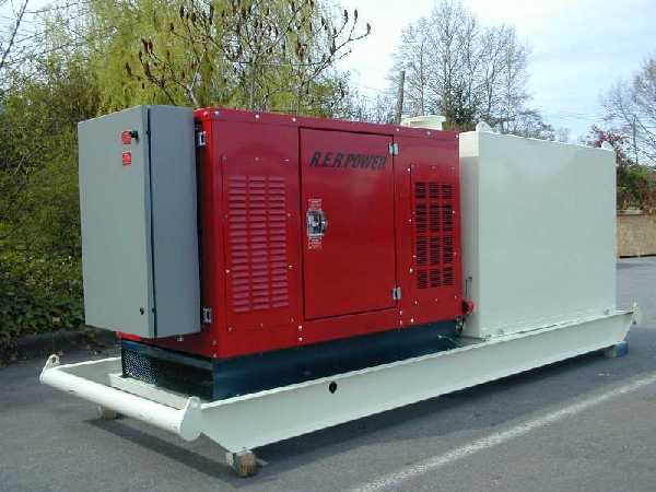
Enclosure
The
enclosure is designed to allow sufficient air to flow to the unit even if one
side should become blocked. (Ice storm, leaf build-up etc.) The panels at the
radiator end are removable for servicing the main cooling fan and motor. Always
replace these panels after servicing.
The enclosure is "rodent proof",
as supplied. It is very important, both for safety and for operating reasons,
that all sheet metal and guarding remains properly fastened and in good
condition. The powder coated outer and inner surfaces protect the metal from
deterioration. Touch up scratches and chips with automotive enamel paint. |
|
AC Electrical Equipment
The generator is brushless and has a solid state automatic voltage
regulator. Generally, no generator maintenance is required before the engine is
due for major overhaul.
A main circuit breaker protects the generator
from electrical faults and branch circuit breakers are provided on all
circuits.
All components of the electrical
system are bonded and a grounding lug is supplied. The unit must be grounded in
accordance with local regulations.
Control and Metering
A control module is
installed which provides engine and generator monitoring functions. As, well
the control module supplies signals to various engine subsystem tasks. For
details, the specific manual is provided. Wiring details are shown on the
wiring schematics.
A reset feature can be used to count down hours to
the engine's service intervals. As well, the control module stores accumulated
kilowatt hours and total running time.
Fault monitoring, with adjustable
parameters, allows the control module to alert a designated operator, via
wireless modem should an alarm or critical fault occur.
Fuel Tank and Skid Base
The fuel tank is a single
wall reservoir with approximately 500 US gallons of capacity. A 2" NPT filler
neck is surrounded by a splash guard. One fuel level sender is provided to
pre-alarm low fuel level. Locks are provided to protect the
contents.
Extreme care should be exercised when filling the tank to
prevent foreign materials from entering the fuel system. Under normal warming
and cooling cycles, condensation will form within the tank. This water will
settle and can be drained off the bottom of the tank via the drain valve
supplied.
Shutdowns and
Alarms
Situations that would result in an engine failure are monitored
and, at a predetermined point, will result in the shutdown of the generator
set. These conditions are; low oil level, high oil level, low oil pressure,
high coolant temperature, engine over-speed and engine under-speed.
In
addition to the shutdown points there are predetermined alarm parameters. At
the alarm point, a signal can be generated to notify the operators of
potentially dangerous conditions. These conditions include; low fuel level,
over-cranking of the starting motor, sender failure (oil pressure, coolant
temperature), high or low speed signal, low battery voltage, battery
over-voltage, generator overload and scheduled maintenance due. |


|